How we teach computers to do additions
Computers are really good at calculation. Well... they are computers after all, right?
But how do they know what "addition" means?
We had to find a way to be able to give them two numbers, and to get their sum as a result.
We're going to see what computers actually do when we ask them to perform an addition, and we will even build our own circuit that adds up integers of any size!
# Logic Gates
We are going to use (virtual) logic gates, because they are a nice way to abstract ourselves from the transistor level and use logic operations directly (logic gates can easily be made with transistors).
Some logical operations we could implement are AND, OR, NOT;
They will allow us to reproduce with a good accuracy the way computers work and how we can help them to count.
The way a logic gate works is pretty straightforward: we give some input(s) to the gate ( wire with or without electrical current ) , and the gate gives as an output in the form of electrical current too.
But let's view them in action to see what they can do: I will quickly present a few logical gates, with a truth table and a little circuit simulation that I wrote in JavaScript, where you'll see the diagram representation of the gate, with switches you can click (the inputs) and bulbs that will show you the output. I hope this will be helpful :)
# The NOT Gate
This one is really easy, it takes one input and returns the opposite: if the input is positive the output will be negative, and vice versa.
| Input | Output |
|---|---|
| 0 | 1 |
| 1 | 0 |
# The AND Gate
It takes two inputs, and the result is positive only if both of the inputs also are:
| A | B | Output |
|---|---|---|
| 0 | 0 | 0 |
| 0 | 1 | 0 |
| 1 | 0 | 0 |
| 1 | 1 | 1 |
# The OR Gate
No surprise, the result is positive only if at least one of the inputs is:
| A | B | Output |
|---|---|---|
| 0 | 0 | 0 |
| 0 | 1 | 1 |
| 1 | 0 | 1 |
| 1 | 1 | 1 |
# The XOR Gate
You might not know this logical operation, XOR, or exclusive-or, means that the output is positive if only one of the inputs is positive (so, it's like "A or B" without "A and B" ):
| A | B | Output |
|---|---|---|
| 0 | 0 | 0 |
| 0 | 1 | 1 |
| 1 | 0 | 1 |
| 1 | 1 | 0 |
# The NAND Gate
The NAND gate corresponds to not-and, it is the opposite of the AND gate: it will therefore give a positive output when at least one input is negative
| A | B | Output |
|---|---|---|
| 0 | 0 | 1 |
| 0 | 1 | 1 |
| 1 | 0 | 1 |
| 1 | 1 | 0 |
Nand gates (and NOR gates) are functionally complete, which means you can build any logical circuit using only such gates. We won't be using them, but it's nice to know that we could use only NANDs to get any kind of logical operation done :).
# Let's add bits: the Half-Adder
The first circuit we will build is called a Half Adder. It will allow us to give two inputs to the circuit, and get the result of their addition, in binary.
Our circuit will have two outputs, and we will use one of them for units , and the other one for the twos .
Here is the result we expect:
| input A | input B | twos output | unit output | Corresponding Binary operation | ||
|---|---|---|---|---|---|---|
| 0 | 0 | 0 | 0 | 0 + 0 = 0 | ||
| 0 | 1 | 0 | 1 | 0 + 1 = 1 | ||
| 1 | 0 | 0 | 1 | 1 + 0 = 1 | ||
| 1 | 1 | 1 | 0 | 1 + 1 = 10 |
you can see that the result will be the sum of A and B.
Now if we take a closer look at the outputs, we can see a recognizable pattern that we saw with some gates we talked about: indeed, the unit output corresponds to a XOR operation on the inputs , and the twos output corresponds to an AND operation!
So we can build the following circuit:
You can play with the inputs to check how the signal is modified and it's effect on the outputs.
We now have a circuit that is capable of producing the sum of two bits:
- If all the inputs are
off, all the outputs will beofftoo; - If only one input is
on, no matter which, then theunitoutput will beon - If both outputs are
onthen thetwosoutput will beon, and not theunitone.
Awesome, we can count from zero to two!
Well all right, I can understand if you're not convinced yet. But billions and billions are almost there!
# One step further: the Full-Adder
Now we need to step back a little bit.
We have our great half adder, it does it's job pretty well: adding two bits. But what about larger numbers?
We will want to add other numbers, and we need a more general kind of circuit for that.
The full-adder will be our building block for that purpose:
It's a circuit derived from the Half-Adder, but we add one input and rename the outputs:
Three inputs:
- Carry in
- Bit A
- Bit B
and two outputs:
- Output Bit ("unit")
- Carry out ("twos")
The circuit will sum up the three inputs, it's almost the same as the Half-Adder:
- if no input is
on, no output is; - if only one input is
onthen only theunitoutput will beon - if two outputs are
on(again, we don't care about which inputs, we just do their sum), then only theCarry outwill be on, - and if all three inputs are
on, then both outputs will beon.
We renamed the twos output because we don't want our full adder to deal with it by itself:
To put things in another way, the core of the Full Adder is the inputs A and B , and the unit output.
And then, the Carry in and Carry out are there to allow the chaining of several adders: that's how we can calculate numbers larger than two.
(the carry is indeed the same one as when we write an addition on paper, and an adder's carry out will be connected to another adder's carry in , we'll see that below)
# Additions
Here is a quick remainder on the fact that binary additions are the same than decimal ones:
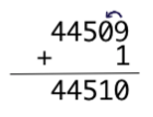
With our decimal numbers we have to carry when the sum of the two digits is more than 9:
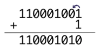
And with binary numbers, since each digit can only be 0 or 1, we have to carry when the sum is bigger than one:
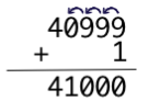
and we need to keep doing it until we can actually stop:
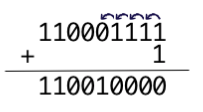
and in binary:
And this is exactly what the Carry inputs/outputs are going to do for us.
# How it's going to work
Let me present to you our first version of the full adder:
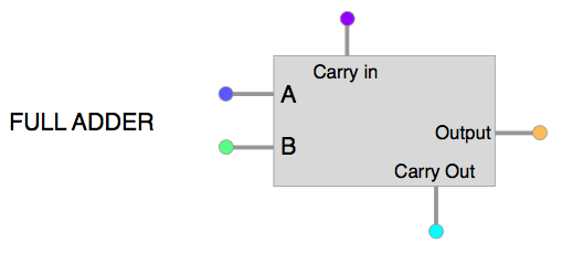
Yes, this is just a black box for now, because we will first be sure to understand what we want from it:
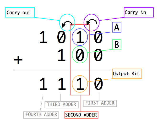
each Full-Adder will take care of one order of magnitude in the operation: in other words, each Full-Adder handles the digits of one column of the addition, taking the carry (if needed) from the previous column, and sending it's carry (if there is one) to the next column.
Here is a -poor- representation of an addition as we would write it, overlayed by the action of each part of a full adder:
And This is how they connect to each other:
# Building the thing
Okay, it's time to get it done.
here is the table of truth we want:
| input A | input B | Carry in | Carry out | Output Bit | |
|---|---|---|---|---|---|
| 0 | 0 | 0 | 0 | 0 | |
| 0 | 0 | 1 | 0 | 1 | |
| 0 | 1 | 0 | 0 | 1 | |
| 0 | 1 | 1 | 1 | 0 | |
| 1 | 0 | 0 | 0 | 1 | |
| 1 | 0 | 1 | 1 | 0 | |
| 1 | 1 | 0 | 1 | 0 | |
| 1 | 1 | 1 | 1 | 1 |
You shouldn't even really look at it actually, that's a lot of numbers everywhere.
To achieve this result, we will need two Half Adder ( who would have guessed? :) . I will not discuss the logic of it, because it is pretty straightforward and way easier to understand by playing with it and studying the diagram.
Here it is, our magnificent Full Adder!
With one full adder we can't achieve much more than what we could do with one half adder.
But with several of them, the dream comes true :)
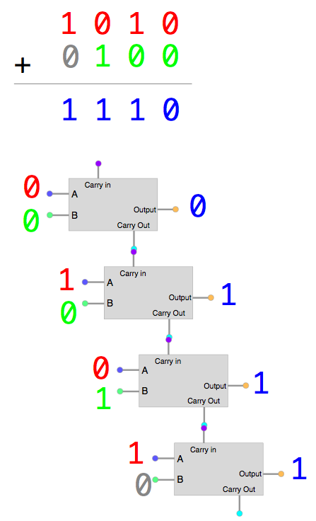
# 4-bits Full Adder
Finally we can start to add up bigger numbers.
With a 4 bits adder, we can deal with numbers up to 1111 (binary), that is 15 in decimal!
The thing is taking quite a lot of space, but I still want to be able to see the path of each wire for this one, so I put the adders in a diagonal way.
You can zoom on it, it will still render nicely.
The corresponding additions are written under the circuit, both in binary and decimal, so you can easily see what is happening.
Also remember that this little program is NOT using any '+' or any mathematical calculation to find the result: it is only designed to simulate the circuit that is drawn, and it writes the corresponding numbers from the values of the little bulbs (the outputs of our circuit)
The leftmost inputs represent the first number to add, and the rightmost ones the second number.
# n-bits Full Adder
Now that we have done that, we can build circuits of the size we want, that will be capable of adding any integer, for example a 64 bits Full Adder can handle numbers from 0 to 18,446,744,073,709,551,615 !
Just for the fun, you can generate a circuit of the size you want here:
# Related links on the WWW
Numberphile will never disappoint us: